
www.indo-industry.com
05
'12
Written on Modified on
Tested With Safety
Automated Testing Equipment for Photovoltaic Central Inverter
As early as 1983 Soma developed automated testing systems for different Eaton devices such as PKZ, RMQ, DIL, NHI, RHI and high rated contactors. Compared to test equipment for the automotive industry, where test voltages mostly never exceed 24V, the voltages required for central inverters, with up to 1000VDC and currents of several hundred amps, need new methods in operating testing equipment safely.
Test circuit
The testing of a central inverter requires the simulation on the input side (DC) of a PV installation with a string voltage up to 1000 V and an output current up to 500A. On the output side (AC), the central inverter feeds into the lowvoltage network with a supply voltage of 400V or 525V. The output current of the central inverter can be up to 350A per phase. The PV installation is simulated by an air-cooled DC supply with an integrated voltage and current regulator. The grid is simulated by the AC side of the central inverter feeding into the rectifier and thus completing the power circuit. The heat dissipation is caused only by the rectifier and the central inverter. An NZM3- 315A circuit-breaker handles the grid power supply into the test circuit.
Test object
The test objects are the central inverters of KOSTAL Industrie Elektrik GmbH. Central inverters convert the direct current of a PV installation into AC current for feeding public or private grids. Ten device versions are to be tested: Starting with the smallest PIKO40 inverter, for PV output ratings of 42 kW, up to PIKO155 for output ratings up to 155kW. All devices are implemented without a transformer and achieve efficiencies of over 98 percent. Each device is tested extensively before shipping. Relevant test criteria are the temperature (steadystate temperature) of individual components, with the central inverter at a permissible ambient temperature of 60°C (IP55). The capacitors in the central inverter are also tested and the response in the event of 100 percent load shedding. This is followed by tests on different grids with regard to voltage, current and frequency.
Automated parameterization via Profibus DP
The feeding from the central inverter into the “grid” is implemented by an NZMN2 or NZMN3 compact circuit-breaker with electronic release, depending on the inverter rating. The short-circuit and overload releases of the circuit-breakers are parameterized automatically for the rating of the central inverter being tested, so that system and cable protection are reliably ensured, as well as the protection of the testing personnel. This ensures during daily routine testing that trip parameters are set correctly for the cable crosssections connected.
Practical issues in detail: Depending the rating of the central inverter, this is connected with the necessary cable cross sections to the feeder terminals of the “grid”. Each power cable is also assigned a signal cable that is connected with an I/O module. The information about the cable cross section is sent to the connected IPC via the signal cable. The project software stores the overload and short-circuit parameters of the circuit-breakers according to the cable cross sections. These parameters are now automatically transferred via Profibus DP.
A Data Management Interface (DMI module) with a fieldbus interface (NZM-XDMI-DPV1) provides the communication via Profibus DPV1 between the Eaton compact circuit-breaker and the PLC. The NZM-XPC-DTM (Device Type Manager) software and the FDT frame application (FDT Navigator) provide the following functions: Firstly, diagnostics, monitoring, parameter setting and switching – which can all be carried out remotely. Secondly, display of circuit-breaker switch position (On/Off/Tripped), phase currents as well as parameter, status and diagnostics data. Thirdly, the setting of trip parameters, and fourthly the assignment of the DMI inputs and outputs, can be used for the activation of the circuit-breaker remote operators.
Documented test results are essential. For this the diagnostics functions of the NZM circuit-breakers with which ten diagnostics items can be read out and displayed as a history log are ideal: Date/time, phase state, cause of trip and the parameters used at the time of the diagnostics event. All project and online data can also be exported to an XML file and added to the test report.
Conclusion
“When we started the project for power inverter test equipment we were entering unknown territory,” explained Wolfgang Thater, head of sales & project engineering at Soma. “It required the control of voltages up to 1000V and currents up to 500A, and at the same time we had to ensure maximum safety for the testing personnel during operation. Thanks to the close collaboration with the product specialists from Eaton, we were able to overcome all technical obstacles successfully.”
The Company: www.soma.de
Products: NZM circuit-breakers
DMI data management interface
DIL contactors
SOMA GmbH is based in Schalksmühle and was founded in 1973. Since 1983 the company has belonged to the KOSTAL Group and develops testing and automation systems. The product range stretches from laboratory systems to check products against specification and test-rigs for carrying out endurance testing in association with product design and development, through to fullyautomatic end-of-line functional test systems. In automation technology, SOMA offers solutions ranging from flexible manual workstations to bespoke rotary or linear transfer systems to fully automated assembly lines with flexibly integrated process modules. Since the beginning of 2009, the range has included components and systems for handling and metering industrial lubricants.
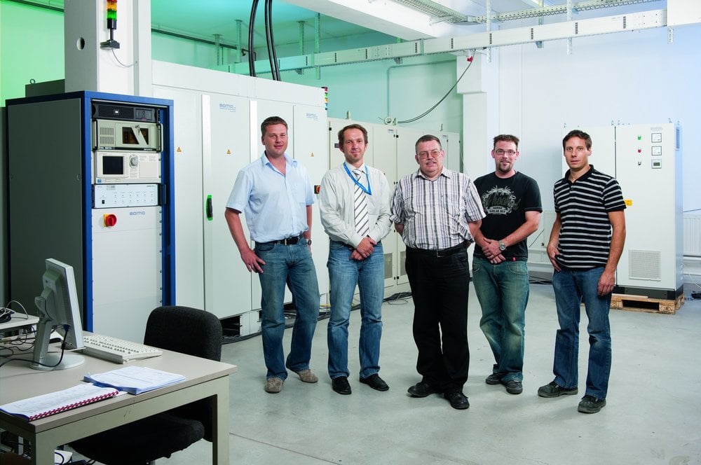
EM_SOMA-5267_cmyk.jpg: The development team of the inverter testing system
From left to right: Frank Landwehr from KOSTAL Industrie Elektrik GmbH, Wolfgang Thater, Frank Berges, Marc Schell from SOMA GmbH and Thomas Körfer from KOSTAL Industrie Elektrik GmbH.
Montage_S21_01_cmyk.jpg: The incomer switch connection of the test objects for grid simulation
The tripping parameters of the circuit-breaker are set automatically according to the cable crosssections connected.
EM_SOMA-5286_cmyk.jpg: One of the test objects
Kostal central inverter PIKO105, 110kW
